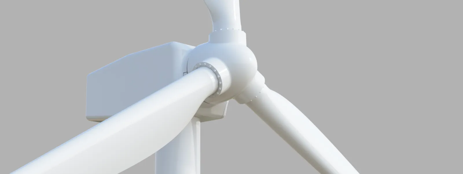
Motorized wind generator
This is a model of a typical European land wind turbine.
Its height from ground to blade tip is 521mm, blade length is 200mm. Since real-world wind turbines vary in side widely, the model can be used on dioramas and layouts of different scale: H0 (1/87), TT (1:120), N (1:160), probably Z (1:220).
Video in action and assembly instructions:
The model can be printed on a typical 220mm printer bed (e.g. Ender 3 or Prusa). The tower itself is split into 3 parts, upper parts should be glued together, the lowest part is held via friction, so that the upper part of model can be rotated or detached from the layout for transportation.
3D model can be bought here: https://cults3d.com/en/3d-model/architecture/wind-turbine-model-520mm-height-motorized.
Features
Motorization
The model is designed to be motorized with an N20 gear motor, which have very good price-to-performance ratio. I’ve tested several gear ratios and voltages, so far 60 RPM 12V motor powered with 5V produces very good results. Downvoltage to 5V makes the operation very quiet (to make it quieter, lubrication is advised). 5V is also easy to obtain from, e.g. smart phone charger or a power bank. The motor I was testing draws around 10 mA of current (yes, 10 mA). It can also work directly from 3.7V of a Li-Ion battery.
Motor should be wired so that the blade spin clock-wise (if you look at the model from front). If they don’t, then swap the motor wires. If you want it to rotate counter-clockwise, print the blades mirrored.
There is a guideway to place an LED on top of the nacelle. It is not a through-hole by default, so you need to drill the hole through the surface. I tested with 0805 SMD blinking red LED, the result looks very good (shown in the video). 3mm through-hole LED can be installed if you increase a hole to 3.2mm by drilling. Place the resistor near the LED, then you can power both the motor and LED by one pair of 5V wires. Flyback diode across the motor is also recommended.


There is space inside the column to place a 2x2.54 connector, so that the top part can be separated from the bottom for transportation.
Part list and assembly details
Part list:
-
1x N20 DC Gearmotor (12V, 60 RPM), sample link: https://www.aliexpress.com/item/33022320164.html
-
1x M3x16 countersunk screw
-
Parts 1.1 (or 1.1B), 1.2, 1.3 for the tower.
Part 1.1B has M12 thread at the bottom, so it can be screwed to the layout. Part 1.1 just has a 30mm height 12mm diameter mounting tube and needs to be glued to the layout. Glue parts 1.2 and 1.3 together, but do not glue 1.1. The upper part is designed to be friction-fitted into lower part, so that the model can be disassembled for transportation of the layout or rotated. The electric connector needs to be placed in the cavity in the lower tower part (see picture)
-
Parts 2.1 and 2.2. Glue part 2.2 to the nacelle. No glue required, top slides into slot in the bottom and is secured by M3 screw.
-
Parts 3.1 and 3x 3.2 for the fan. Glue blades into the hub with CA, epoxy or PVA. Fan is friction-fitted to the shaft of the motor.
Printing details


Layer height
-
0.08mm layer for the blades for highest surface quality.
-
0.2mm layer for other parts
Orientation and supports:
Print blades thin long edge facing up. Blades need supports. Nacelle top needs to be printed upside down. Nacelle bottom requires supports if you print it upwards, as not all of the bottom surface touches the bed.
Other parts are printed upside up or on your discretion according to your printer capabilities. They don’t need supports.
| File "Hub" is exported as-designed and is not parallel to build plate! Use "Lay flat" function in your slicer. |


